Schematic Driven Layout
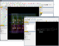
The LayoutEditor will normally start with the layout window. To get the schematic window you can ether open it via Menu/Utilities/Netlist Tool/Schematic from the layout window, start the LayoutEditor with the option '--schematic' or use the 'juspertor library manager' of the pylayout python module. Similar to the layout window the schematic window has a drawing area in the middle and a mouse help usually located in the lower left corner. Above the mouse help there is a window to manage the components or devices required by the schematic.
Managing Components
 Requirement for these feature is a component/device library which contains all information (symbol, layout, netlist, ..). Some library (like Open Cell Library) are included in the LayoutEditor. Further libraries can easily be created or OpenAccess libraries including IPL&iPDK comptible libraries can be used. Native LayoutEditor libraries are ASCII file which can be ether edited by a text editor or can be modified via the component manager. Before placing or importing a schematic all required components had to be created. Information from some other libraries formats can be imported by the component manager.
Schematic Driven Layout: Principle
 From the layout window a schematic window can be opened (Menu/Utilities/Netlist Tool/Schematic or from the toolbar). Also from the schematic window a layout window can be opened. Open the windows in one of these kinds will create strongly linked windows: The schematic is syncron with the selected cell. Change/rename a cell/schematic sheet will also change rename the sheet/cell in the other window. For each device in the schematic window a cell with the layout of the device will be created. Clicking on a device will hightlight the cell/device in the layout, if it exists. If not, the place device mode will be activated. If you change a parameter inside the schematic window, the layout of this device will be adjusted in the layout window. Also the routing is linked: Clicking onto on node in the schematic window, the required connections will be displayed in the layout window.
|
Setting up the Technology/Layers
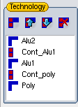
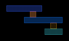
 For routing a schematic in the layout window some information on the connecting layers are required. Enter all connecting layers and associated via layers to the technology list and sort them in the correct order. The setup display on the right will represent a technology as displayed on the left. The lowest display layer is the "poly" layer followed by the "Cont_poly" layer and so on. The library and technology setup will be saved on program exit and restored on program start. Also the setup can be saved via the Generate Technology Macro function.
See also

