3D View
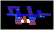
 A two dimensional designing can sometimes be quite abstract. The LayoutEditor allows a fast three dimensional visualization for your design. The graphical setup can be done in few seconds. The 3D model/3D view can be exported and used for example for a FEM-analyse.
Extrude from the 3d setting of layers
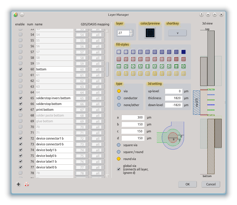
 The fasted way to get a 3d model from your design is to use the 3d setting of the layers. These 3d setting will be used to extrude the corresponding layers and add it to the 3d view.
Prior to the use this way a setup had to be performed. A thickness and level of any layer had to be defined. This setup can be done in different ways:
by the LayerManager,
via the LayerButtons of each layer,
- by a cross section drawing .
The simplest way may be the last one: draw a cross-section view of your technology in a separate cell/library and press the Setup3D button. All required information is extracted from the cross-section. Afterwards select your cell and activate one of the render functions.

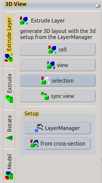
After the setup you just need to trigger the 3d rendering. There are different ways for the rendering:
RenderAll - all visible shapes of the current cell are displayed,
RenderView - only the current view of the current cell is displayed,
RenderSelect - selected elements of the current cell are rendered.
Alternative 3d generation
Next to this more or less automatic way to generate a 3d view it is possible to generate the 3d view step by step by using different 3d features like Extrude, Rotate or InsertModel. All available 3d features are listed here. Any of the 3d features can also be used from the macro interface. For details to this please see MacroClassView3dModule and Macro 3d Editor Classes. For PCBs and the OpenCellLibrary ready to use 3d view macros are shiped with the LayoutEditor.
Example
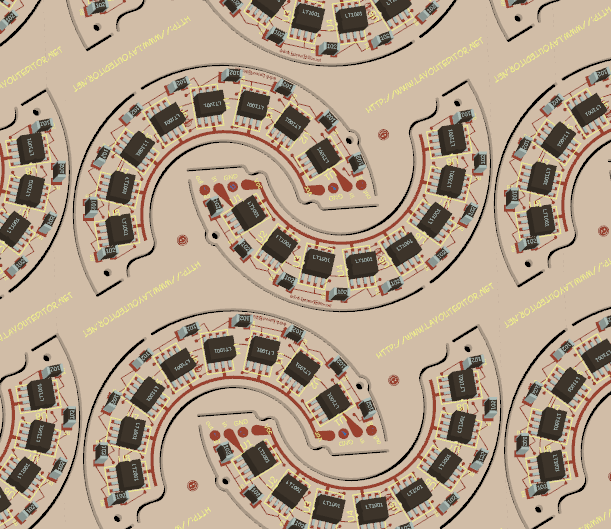
3D view of a printed circuit board:

