The SchematicEditor
There is a lot of different schematic software on the market. Most is designed for a special application like entry for simulation, schematic supported layout generation or just for documentation. Some software is limited to PCB or to IC circuits. The SchematicEditor does not have these limitations and combines all listed applications. Futhermore is can be used for a Parametric Mask Layout together with the LayoutEditor. This makes it a versatile tool for all types of applications -- IC, MEMS, PCB, Microwave, ... Prepare to be impressed!
Designing Schematics
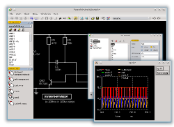
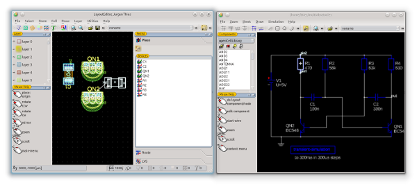
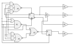
A comfortable editing with a intuitive user interface is important for a SchematicEditor as well. The design of the user interface in the SchematicEditor is similar to the LayoutEditor. So also here an outstanding usability is achieved, plus a big synergy effect, if you use both LayoutEditor and SchematicEditor. |
|
Supported File Formats
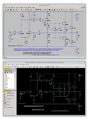
Versatility is not just a question of available feature, but in particular a question of cooperation with other software. In order to achieve the maximum possible here, a large number of file formats for schematics, netlists and libraries are supported. Thus, for example a schematic created with LTspice can be loaded into the SchematicEditor directly. (see screen shot on the right). |
|
Besides its own format for storing schematics and libraries these file formats are supported: |
|
Additional any text based netlist format can be created. Just a simple setup is required to define a further format. Also any schematic can be converted to the layout window. So it can be exported to a wide range of graphic formats for documentation. |
|
|
|
|
Simulation
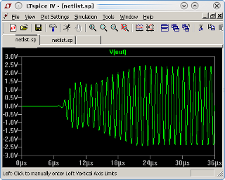
A common design flow is to design a circuit, simulate and optimize it, create a layout and verify it. To follow this flow the simulation part in the LayoutEditor/SchematicEditor is missing. But this is not a problem as the SchematicEditor works together with many external simulators. So the circuit can be simulated with more than one simulator and the simulation results can be compared. The simulation can be triggered from inside the SchematicEditor. Doing so a netlist will be generated, the simulator be called and after completion a wave form viewer can be called by the SchematicEditor. The hole sequence is controlled by a macro and can simple be adjusted by anyone. Complete and tested macros are shipped for some common simulators like HSPIE, LTspice, ngspice or Qucs and need no more (or minimal) setup to use. |
|
Schematic Driven Layout
Creating a layout from a schematic is a widespread task where EDA software is used. The SchematicEditor is linked with the LayoutEditor, which enables a comfortable schematic driven layout. Place/choose a device in the schematic window and simple move the mouse to the layout window to get the corresponding device design. Select a node in one window and it is displayed in the other window. These features support the design without restricting a free custom design. |
|
Layout Versus Schematic
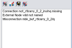
Validating a design is normally one of the last steps. The combination LayoutEditor with SchematicEditor supports this. A netlist can be extracted for a build-in or external layout versus schematic (lvs).The build-in LVS make it very simple to follow up an error. |
|
Documentation and more
There is much more to say about SchematicEditor features. Please have a look into the documentation especially on the list of all Schematic Features. Or just try it out and be impressed! |
|
Still anything missing? No problem! New ideas to improve the SchematicEditor are always welcome! Please leave a note or contact: ideas@layouteditor.net |


