Design Rule Checker
Verifying a design can be a complex task. A automatic design rule check is the standard for many years in the area of IC design and it is getting more and more standard in the area of MEMS, Microwave,PCBs, etc. A versatile Design Rule Checker is integrated into the LayoutEditor. A complete design check can be triggered by calling a DRC macro. Also any single check can be called manually. The LayoutEditor supports many different design rule checks. More checks are supported than a simple IC design requires. For all tests the area to be checked can be specified as well as the way rule violations are reported. As a matter of course, all design rule checks work on all angle elements. Design rule checks are not intended to check Multi-Gigabit designs, it will leak on performance but will work if you have a powerful system and enough run time to operate. Designs with up to over some million shapes are no problem, even if computationally intensive options are used.
Illustration

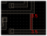
Graphical Illustration
The basic concept of a graphic violation display is: A new cell will be created named as the checked cell and the name of the design rule check. All detected errors are added to this cell on an error layer. A new cell reference to this cell is added to the unmodified original cell. If an identical check was performed before, the earlier results are deleted. Use ClearDRC to delete any prior results.
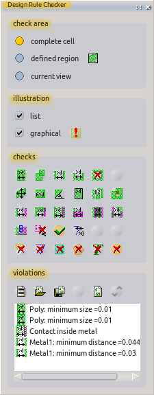
Listing Violations
A list will be generated showing each detected violation, with one violation per line. Each line contains the symbol for and name of the check; and, where applicable, the measured value. By clicking on the list, the current view is directed to the diagrammatic location of the violation. A double click will mark the entry. The violation list can be stored and loaded. The violation list can be be deleted manually or by a macro.
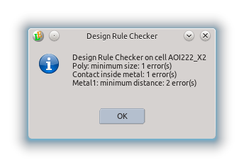
Summarizing Report
Aside from the graphic display and a full list with all errors, there also is generated a small report with a summary of these errors. This report contains the aggregate of all errors for each check.

Check Area
The area being checked can be defined. It can be the whole cell, limited to just the current screen view or a user-defined region. If the check region is limited, all applicable violations in the check area will be found. Depending on the type of check, some violations near the border region also may be displayed.
List of Design Rule Checks
DRC Macro
Each DRC check available in the user interface performs only a single check. A complete DRC usually requires many individual rules. For a complete DRC in a single step, a macro must be created with all the necessary rules folded into it. When doing so, each rule can be given an individual name. This macro shown below provides an example. It represents a part of the sample macros shipped with LayoutEditor.
   1 #!/usr/bin/layout
   2 #name=Macro: drc example.layout
   3 #help=example for a drc macro
   4
   5
   6 int main(){
   7
   8 layout->drcTool->result="DRC (LayoutEditor example) \r\n";
   9
  10 // setup error layer
  11 layout->drawing->activeLayer=0;
  12 layout->drcTool->setErrorLayerToActiveLayer();
  13
  14 // check for layer metal 1
  15 layout->drcTool->ruleName= "Minimum Size Metal1";
  16 layout->drcTool->minimumSize(800,6,true);
  17 layout->drcTool->ruleName= "Minimum Distance Metal1";
  18 layout->drcTool->minimumElementDistance(800,6,true);
  19
  20 // check for layer metal 2
  21 layout->drcTool->ruleName= "Minimum Size Metal2";
  22 layout->drcTool->minimumSize(900,8,true);
  23 layout->drcTool->ruleName= "Minimum Distance Metal2";
  24 layout->drcTool->minimumElementDistance(900,8,true);
  25
  26 // check for via1  (metal1 to metal2)
  27 layout->drcTool->ruleName= "Via in metal1";
  28 layout->drcTool->inside(50,7,6);
  29 layout->drcTool->ruleName= "Via in metal2";
  30 layout->drcTool->inside(60,7,8);
  31
  32 layout->drcTool->showReport();
  33
  34 }

